DODGE CARAVAN HEATER FAN (FORWARD)
I presume you have a service manual, though I may include brief pointers from it to make this advice more cohesive. Some of what I cover here is in the service manual if you can find it, often not in the section you'd expect it in - check both the instrument panel and specific-item sections.
Diagnosing heater fan:
- Resistor assembly is on front of firewall pax side.
- See below for wiring to fan, behind glove box
- This system is typical in that it has vacuum actuation of some of the doors and flapper valves that control airflow, and air recirculation in Max A/C mode.
- There is a Service Bulletin on stiff heater controls, detailing drilling in from the side of the centre dash to lubricate. Perhaps 240394 or 240594A, both addressing diagnosis of heater performance.
To replace the heater/AC blower:
Preliminaries:
- the Chrysler service manual is not joking when it instructs you to remove the entire dash & structure, this is a difficult job, especially with having to remove the passenger airbag. I tried to proceed without doing that, but it may not have been the easier way:
- remove the glove box (the two door-restraint cords snap out of the lid when the serrated tab is moved a certain way; in addition to the washer-head Phillips-head screws holding the glove box to the dash panel there are two small hex-head screws holding both to a piece of structure). Disconnect the light to keep it off (use finger to pry up tab on top of connector).
- you want to avoid trying to remove the main dash panel, aka "lower right instrument panel", as it extends across the heater-controls area to the end of the left dash panel and contains the passenger airbag. (That might allow you to move/remove the heater duct and upper fan housing enough to get at the bolts holding the lower fan housing.)
- ALSO BE CAREFUL WITH WIRING AS THE PASSENGER-SIDE AIRBAG IS ABOVE (the normal precaution is to disconnect the vehicle battery)
- a light-weight horizontal panel under the blower-duct area snaps out of place and/or is press-fit, depending on the side of the panel in question
The pieces and tools:
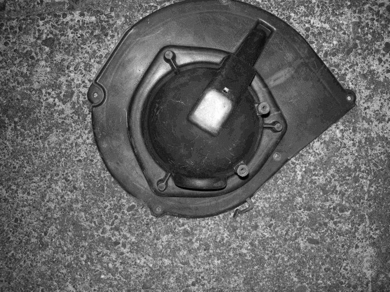
- through the glove-box opening you can see a plastic cylinder, with a join line at the bottom. The fan is in and secured to the part below the join line, which drops down once unbolted. We hope. Here's a look from below showing the domed lower fan housing (forward is top left, aft is bottom right, the join line is where the shade of plastic colour changes slightly). You can see the trim clip on the bottom, two 10mm screws holding dash structure to sidewall bracket (bottom left of photo), two screws holding the wiring bracket (bottom centre of photo), and even a missing dash trim-structure screw location (plus various wiring getting in the way).
- SCREWS: pointed screws with 8mm hex head are located at aft center, mid right, forward centre against the firewall a bit to the right, mid left, and aft left. (Here's a picture of the bottom of the lower housing, flipped left-right, aft at bottom of view; note the wiring clip on aft edge.) Screws holding the bottom edge of the panel structure to the body sidewall bracket are 10mm hex head, one hidden higher up should also be removed (plus another somewhere?), plus a large long ?? head screw holding a side structure bracket to the body sidewall. Screws holding the fan assembly inside the lower housing are 1/4" hex head. (Note the trim clip on bottom centre of the fan housing can be left in place.)
- now prepare yourself for a long awkward job:
> gather a quality 1/4" ratchet wrench (small head diameter and consistent light ratchet action), long & short extension bars, plus 8mm, 1/4", 10mm, and ?? sockets, as well as 10mm open end wrench, and a puller such as a webbing strap ratchet, 1 1/4 inch wide or so with simple hook ends. (A problem with sockets and closed-end wrenches is that the hex heads on the screws are shallow and the edge of the socket/wrench opening is chamfered, thus there is little tolerance for not having the socket squarely on the screw. Once you get the socket squarely on the screw keep upward pressure on it while avoiding tripping the usual direction lever. Oh, and make sure you keep your ear to the ground, nose to the grindstone, and .....)
> position a bench outside the open right door, level with the sill, and some cushioning pads for your back as you lie on it. (Though the forward corner screw may require being right side up, at least being able to reach around the fan housing. You'll be working by feel on the difficult screw, in any case.)
> schedule a few hours
> obtain ample patience
The Job:
- onward to the bolts:
> The aft center one is difficult to remove as structure prevents sticking a wrench extension straight up, and wiring interferes. You can remove the two screws holding the bottom of the panel structure in place and pry it away a bit. (See later need to pull the whole structure aft to get the fan out.)
Ideally you have a "flexible rod" extension, otherwise try a rigid extension with swivel adapter on end, but tape or tubing over the swivel adapter to stiffen it (you want to get it to the screw head then push up to align it, a normal swivel just flops around). You should be able to see the screw head through the glovebox opening, just, to see where your wrench socket is.
> The one in the forward right corner near the firewall is very difficult to work on, as it is too close to the firewall so needs a ratchet wrench with small head diameter, has little space to swing a regular wrench, and has the fender well below.
You can get one hand in the slot between the fan housing and the firewall, from the left, or one hand in the slot between the fan housing and the sidewall. You are operating blind, so it is difficult to sensure the wrench is actually on the head, and you cannot grip the screw with fingers once it is partly out - that's why you need quality in the ratchet, so its back-drag is minimal and consistent (but you're less able to hear it as well, thus don't realize you are just yo-yoing as it is easy to hit the lever that reverses the ratchet action). (Taking the seat out might let you get both in at the same time - isn't this easy? ;-)
Hopefully your hands are small (or you can recruit a person with small hands who likes to tinker).
One alternative may be a flexible shaft as sometimes sold for drills to position the drill away from the chuck and operate at an angle, if you can get a 1/4" end on it to drive a socket. Then hold the socket in place with one hand and operate your electric drill or screwdriver with the other.
- fan wiring is the green-black pair through the connector at upper center, push on the front side of the upper part to disengage the latch (the lower part is fixed to something - it is removable by sliding a small screwdriver behind it and prying outward to unlatch the slide that is attached (Do not remove the metal bracket is awkward as there is not room for the length of the screw when unscrewed and you'll never get it back in.) The wiring feeds through a large grommet in the lower fan housing, located a bit to the left of the middle of the aft side. (Also notice the wiring in the photo, that you'll have to move aside. The metal bracket with two Phillips head screws is a tall affair holding wiring - you'll need to detach it and move it up past the dash structure and hold it up. Also note the wiring that runs forward to the firewall and another running to the right will have to be pushed out of the way to remove and install the fan housing. Also note the wiring clip on the lower fan housing aft edge.)
- It might help to detach the relay bracket under the ashtray, behind the bin, and move it to the right to lengthen the thick wire bundle a bit.
- Once detached you have to move a smaller wire bundle out of the way and the dash structure aft a bit.
> Take out the two large structure screws mentionned above plus the similar large screw oriented fore-aft up high behind the plastic dash cover (pull it out and use the open end wrench I list above). Also take out the even larger screw oriented sideways into sidewall structure, below the dash, holding a bigger piece of structure.
> Wiring gets in the way, some of which snakes around the end of the dash structure secured by a plastic clip that projects below the lower housing. I pulled the dash facing back a bit and used a chisel to cut off the barbed retainer for the clip. Then I was able to move the wiring up and aft over the dash support structure. (The clip is two-headed but only the right half is used, very difficult to cut at it to unclip the wiring, if you are careful and dexterous perhaps you can get a small screwdriver under the harness and pry it out of the clip.)
> Then I used a webbing ratchet hooked onto the dash support structure to pull it and the facing structure back enough to drop the lower housing with fan. (Because the wheelwell prevents pulling the forward side of the housing down much, the structure must be pulled back enough to clear the tipping fan impellor, using the webbing ratchet attached to dash structure that it won't slip off of and to the door latch loop at the other end.
(According to the service manual, you'd have to take out the passenger airbag module to get the RH dash upper facing off which might uncover the upper structure screws, so I did not try that.)
- Carefully remove the fan impellor from the motor shaft to avoid breaking the boss.
- the motor is crimped together so taking it apart will be awkward, if you want to try to repair it (problem might be brushes but it might be commutator damaged or one or more bars not electrically connected anymore). The following is stamped on the motor housing:
5265 467
70113 0634 B
AY166100-0076
DENSO 13.5V
The following is molded on the fan impellor:
55036170
47230326
18635
The replacement aftermarket unit:
ōCooling Depotö 11135492V on box; Unimotor 12492 12V 06128 (made in Canada) on motor; Wiring appears to be lighter (or & bk pigtails), motor larger
- To replace the fan motor
> Be careful removing the impellor. It has a simple retaining clip but may still be tight on the shaft.
> Ensure you position the new fan assembly in the housing so that the motor cooling hole lines up with the port in the housing. You may have to fiddle with wiring to avoid interference.
> Either buy new gaskets or put a bit of sealant under the gaskets anywhere they are coming loose, so they don't shift while wiggling the housing back in, and on the free side, then let cure.
You have to put it all back together:
- To get the fan housing back in:
> get oriented (square corner of the flange is at forward left)
> slide the left end past the wiring harness and make sure all wiring is out of the way
> get the fan under the upper housing (observe the side of the impellor)
> wiggle and slide somehow (you'll need to tilt it aft edge down as the wheelwell prevents the opposite, get the flange past the dash structure, get the housing aligned so the impeller goes into position, then hold it while getting the screws.
> Positionning the screws to start them screwing in is not especially difficult, getting them started with fingers then using a long extension with short socket, or no extension with long socket. (Get all but that awkward one well started then ensure the housing is centered before finishing.)
> You can get that awkward back one just started with fingers but then need the tools described above for getting it out. It'll go in easier because it is tightening ratchet action all the way, though you have to keep the socket on straight and it will take time.
Don't forget to secure the wire harness if you took the clip off the right end of the dash structure (should be able to sit it behind flange), and reconnect the glove box light.
If you took the trim clip off the bottom of the fan housing, be advised it installs with the open end of the clip pointing aft.
I considered/tried flexible extensions and flat/cranked wrenches to work that awkward screw, but had best success with the basic ratchet and deep socket, it just takes time. (In general you need some clearance below the fan housing flange, which is why the ratchet with deep extension works.)
Do try to avoid what a friend described in his instructions for repairing a clockwork motor from the Meccano toy sets (like Erector, Marklin, etc.). His first line was:
- remove four screws
and his last line was
- replace three screws (you always lose one)
But in fixing my Caravan I often have screws left over. ;-)
For the left lower dash refer to the main Caravan maintenance page subject HIDDEN RELAY PANEL and to the parking brake page.
© Keith Sketchley Page version 2009.05.17 (1901PDT)
Please advise Keith if any links don't work or have become inappropriate - the Internet changes.
Back to Keith's Caravan maintenance page.