DODGE CARAVAN ALTERNATOR REPLACEMENT
This applies to a 1994 vehicle with the 3.3L engine. (The 3.8L version should be the same, 1993 1/2 similar but somehow much worse to work on, but the 1996-onward installation may be worse because cowl overhangs engine bay.) In include air conditioning which complicates access.
You need a service manual, though I may include brief pointers from it to make this advice more cohesive. Study the manual, including Fig. 5 showing the terminal to wiring block you have to move to the replacement alternator.
TABLE OF CONTENTS
Applicability and service manual.
Diagnose First
(Tools for diagnosis)
Tools for replacement of alternator
Alternator models
Belt Tensioner
General & Preliminaries
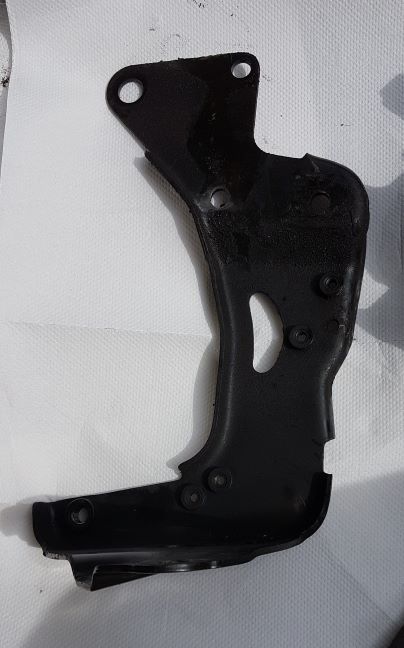
Generator Support Bracket (tall black)
Bottom bolt of alternator
Alternator terminals
Belt tensioner
Better access possibilities
Inside the alternator incl tools
DIAGNOSE FIRST:
Changing the alternator on the Chrysler 3.3/3.8 litre engine is very awkward. Be prepared to go under the vehicle, to work down the back of the engine, and to take off more than you expect. the design is a lashup, jumbling a vertical aluminum piece with a vertical steel piece that goes over the alternator thus has to be removed.
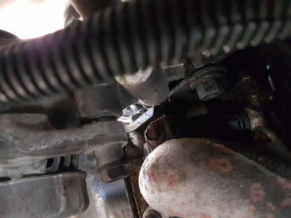
Here is a view of the tensioner-PS bracket from above, note proximity of exhaust manifold (tensioner stud hole is a bit below it to right), and inboard stud for the brace (outboard end bolts to the rear face of the bracket). Tip of spark plug just visible near the stud. Note little clearance from manifold.
Here is a side view of tall bracket looking outboard
So you want to be sure of the diagnosis before you start.
DIAGNOSIS:
TOOLS for diagnosis:
- small file and stiff brushes (one with bristles on end) to clean alternator terminals for meter contact
- good voltmeter, high impedance to reduce risk of damage to sensitive circuits
- narrow alligator clip to reach into output terminal
- wiring diagrams including illustration of alternator terminals (be wary, there are errors in them), note colour coding seems consistent from end to end which helps verify you have identified correct circuit at PCM, circuit numbering is usually consistent but output switches from A11 to A0 and some manuals show A142 as A1 at alternator.
- connector probes if your meter does not have slim points on leads
The alternator is controlled by the engine computer, which should set a fault code, but that may take a while to get set. In my first I had a code 41, problem with control circuit, rapping the side of the alternator with a wrench restored function every time. (Control is by PCM via armature which has slip rings. Whereas code 47 is voltage too low, 46 is voltage too high. Beware that Chrysler varies terms used for the codes.)
I then checked the voltage gage in the instrument panel, but had to check with a hand-held meter as the gage is difficult to decipher (you think that it is 2 volts between marks, but count the marks between 8 and 18!) and not consistent in scaling (seeming to have at least .25 volt hysterisis). It does seem that the marks you'd expect to be 12 (battery close to charged) and 14 (approx charging voltage of typical system) are roughly that.
Resistance of armature is a few ohms roughly.
Resistance of stator TBD (in one direction through diodes, little continuity the other).
Check resistance from output terminal to battery positive terminal, should be very low. (Output should have voltage on it with battery installed.)
Check continuity from armature terminals to PCM connector (cavities 20 (from K20) and 57 (from A142), beware that some Chrysler diagrams do not say whether they are showing the wiring connector from face or wire side, and what some say is wrong).
There should be battery voltage on the PCM connector from one side of armature, the PCM takes the other side to ground with varying resistance.
Check for battery voltage on the PCM connector contact 3.
While you are at it, check grounds on the PCM connector (11 and 12 are power grounds).
If you do not have voltage from alternator output to battery, note there are inline single-circuit connectors in the feed from alternator to battery, a black one behind the battery, a light coloured one somewhere deeper in the wiring harness mess. Some years may have a fusible link behind the battery.
TOOLS TO REPLACE ALTERNATOR:
PREPARE yourself with:
- 7, and 8, 10, 15 deep & shallow, and 18mm deep, sockets
- 8, 15, and 18 mm wrenches preferably ratcheting box end type (box end wrenches stay in place better than regular socket wrenches, you can keep moving the ratcheting type in close quarters)
(- see BELT TENSIONER later on this page for possible additional tools for alternative ways of removing tensioner.)
- large tray under vehicle to catch fallen parts, you can just pull the tray out to reach the part ;-)
- a way to retrieve parts that fell into crevices, such as the tensioner stud nut into a nook below that your fingers have difficulty getting it out of (I have a nifty flexible lighted magnetic one)
- 3/8" ratchet wrench with short extenders and adapter to 1/4" for the small sockets (preferably also a 1/4" drive ratchet for shorter swing clearance and shallower head), desireably a 1/2" ratchet wrench or quite long 3/8" for leverage on some bolts/nuts
- diagram of serpentine belt routing
- belt tensioner tool to relieve tension in belt to pull it off alternator pulley, one version is a flat bar with an unusually short 15mm socket. My belt replacement page for tool options including wrench with pipe extender.
(On some vehicles you have to remove screw holding brake line clamp to get room for that socket and bar, 3/8" hex head not metric size, brakes on this beast use SAE.)
- pliers to move tangs of hoses under back of engine, to avoid ripping your arm up.
- light wire or heavy twist ties or such to hold belt up, and PS reservoir out of the way of getting bracket bolts out.
- very light string or twist ties to hold replacement belt to large rear bottom pulleys while putting it around forward pulleys (new belt is stiff as it has been folded in package, perhaps warming in sun would help), very light in case you forget to take it off, hopefully will break ;-)
- BTW, there's a splash shield that you may have to remove to get at front belt pulleys, that shield does reduce risk of belt coming off from slush onto pulleys
- something to jam between tensioner and frame, to hold it against engine while you go underneath to put the nut on (the wrench blocker I describe in carabelt.htm may be thick enough)
- lights
- small mirror
- photographs I provide, so you understand where thehidden piece is to feel for it.
- opera gloves (well, snug-fitting covering for your arms, as they'll contact dirty pieces reaching in to get at bolts, I wonder if small sizes in those defective Lulemon yoga pants are available? ;-) Perhaps bee keeper goves, you want sturdiness without stiffness. Best would be elbow length leather gloves, but thin, perhaps cut fingers off to manipulate nuts and bolt heads.
- long skinny forearms ;-) (do not put your elbow down the back of the engine, you might get stuck).
- hefty jack and safety stand to raise vehicle as you need to work from below to get the tensioner stud nut off.
- something to stand on to aid reach down back side of engine (I'm trying a sturdy 2-step folding stool, and a small folding work platform, a proper height vehicle ramp would work but those are hard to afford (standard 6-8" ones not high enough).
- cushion to rest head on cowl when you are reaching down the back
- knee pads to cushion when you kneel on the structure above radiator
- small pad to rest left arm on PS reservoir and ignition coil when using right arm to reach to lower alternator attach bolt and RR spark plug, or right hand on when using left arm to reach LR spark plug
You will of course have to remove and reinstall the serpentine drive belt - go to my belt replacement page to see my advice on that, and needed slim tools.
PROBLEM ON MY 93 is that brake line and clamp prevent even short 15mm socket on bar from going into place to engage idler. So removal of it (looks like 10mm screw head) and somehow drilling a hole to relocate will be necessary).
Know in advance this is a very difficult job, you'll be reaching beside and up/down back of engine with poor clearance, with one hand, trying to manipulate wrench into position.
ALTERNATORS
My '93 and '94 4 vehicles have a Denso 120 HS alternator, commonly referred to as 120 amp but specs show 102. (It's in what is called the "120" family, there is a smaller "90" family, one distinguishing feature is the lugs for the ground connections don'ts stick out as far on the 120. There seem to be several variations on the manufacturer's name, especially the prefix such as Nippon, mine had ND on the end cover (Nippon Denso) but the wiring diagram in service manual calls it something else - though see my wiring diagram errors page for errors.) If trying to swap from another vehicle model, note the pulley has to match the belt ("6-rib" in this case)
TENSIONER
You might consider replacing the tensioner for the serpentine drive belt though it is another $80. or more cost, you have to take it off anyway. If you have time/alternate transportation to go get one if needed, you might examine it - I found the old one on my '94 had taken a set relative to the new one (the mechanism and pointer were significantly CW from the new one which appeared to be at fully extended position). I purchased a new one because in reinstalling the belt previously the old one had stuck in a retracted position so the belt was loose, until I whacked it with a wrench. It was more difficult to get the belt back on with the new one, as not stretched and new idler pulley has edges, given the limited tool travel I describe in my page on the belt.
GENERAL & PRELIMINARIES:
Think through sequence carefully, both out and in, especially involving the tensioner, PS pump reservoir hose clamp, tall bracket, and horizontal brace as they get in the way of other work such as tightening bolts .
Looking at the service manual instructions, I make these recommendations:
- With air conditioning and the 4-speed AT (thus a transmission computer on the firewall) you definitely have to remove the big "generator support bracket", there isn't room to slip the alternator aft and up. That requires removing the belt tensioner, removing one bolt of the right engine mount plus loosening another, and removing two bolts further down, and removing three bolts holding the PS reservoir and tubing. (Itself a fiddle job as bolts are hidden, a short 1/4" drive extension and thumbwheel are useful, you have to remove the tensioner to get a wrench on the tubing clamp bolt as it is not visible from below with the tensioner in place. An 8mm closed end wrench with ratchet may speed the job after you get the bolt backed out a ways, before then there isn't room for the end diameter of the wrench.)
Removing the tensioner may necessitate removing a brace from the rib the PS pump and alternator attach to, which stabilizes it to an exhaust manifold stud.
(See the bottom of this page for a possibility of rotating the engine, which is not easy either.)
- consider holding the serpentine belt up so you don't have to spend time later getting it back around the several pulleys and idlers, though it's a fiddling bother to do so especially avoiding swing of belt tension relief tool. (My belt replacement page ruminates on that.)
- but first undo the tensioner stud nut (see below), as removing the tensioner lets you get at the PS tube clamp bolt and the lower bolt of the big "generator support bracket", and the stud goes through that bracket. It goes through both the tall PS pump bracket and the big "generator support bracket", a bit below and forward of the bottom bolt of the alternator (which only goes through the bottom of the "generator support bracket". The tensioner stud nut is outboard and a bit below the heavy 'support bracket' that stabilizes the PS pump bracket to the exhaust manifold, outboard of the exhaust manifold and a bit below its outboard attachment stud - see photo of location.
You can then wigggle the tensioner out and up or down-forward to get it out of the vehicle.
BUT be prepared for even more difficulty getting the tensioner stud nut back on. With luck you can snug it with your fingers, then tighten it with a ratcheting box-end wrench (such wrenches have a limitation that they do not work well until a fastener has substantial friction).
BTW, I had to jack the vehicle again to get an arm in far enough from below, from above I couldn't manipulate my fingers enough to get nut on.
- You have to undo three bolts to move the power steering fluid reservoir, counting a hose clamp lower downout after tensioner and in before it - 8 mm socket. Use a fairly stiff wire to hold it up, perhaps through the end of the jack, or hooked into the top of the shock tower. (Or consider draining PS fluid and removing reservoir and its hose, an opportunity to renew fluid.)
- once you remove the top alternator attach bolt you may be able to swing the alternator forward to easily remove the nut holding the wiring loom clamp to the alternator, and pull the alternator back to more easily get at the other wiring nuts, and get at the bottom bolt (you might have to loosen the nut a bit - 15mm socket on head and 15mm wrench on nut outboard).
- GENERATOR SUPPORT BRACKET (refer to figure 8 in section 8B of service manual text):
- it holds the top of the generator and attaches to the intake manifold
> Note the "generator support bracket" goes on the inboard side of the cast rib structure, held to it by the tensioner mounting stud (oversize hole) whereas at the three side mounting bolts it is on the outboard end of the engine (lower down).
> the forward-most of three bolts (top) attaching the tall "generator support bracket" to the right side of the engine goes through an angle bracket to an engine mount (the SM does not show that). There is a cylindrical spacer between it and the "generator support bracket", to fall out and get lost - the bolt is long, though the spacer may stick in place so make sure it is out. Tip: put a magnet below the spacer. (There's another bolt below the lower two, to be ignored.) And you need to loosen the bracket from the engine mount at it to be able to wiggle the tall bracket out (that's where the deep 18mm socket is needed PLUS 18mm wrench on the head of the bolt, a box end wrench with ratchet worked well). It is awkward wiggling as there are flanges on some lower edges of the bracket.
On reinstallation I had difficulty lining pieces up to thread the long bolt in, a mirror helps - check the second short bolt hole after loosely threading the first short bolt, and loosely thread the bracket to intake manifold bolt in.
> the long black bolt is the top generator attachment, the shorter three hold the bracket to block and manifold.
> and there's one bolt on top holding the bracket to the intake manifold
> and there may be a wiring loom attachment to pry off
> while you have the tall bracket off, replace the grommet for PCV valve hose, it hardens so is very difficult to replace nornally
- BOTTOM BOLT of alternator
> Then you can get good access to the bottom bolt of the alternator, the very long one.
> You can get at the bottom bolt that goes through two lower lugs of the alternator, from above or below, either direction awkward as have to hold a wrench in each hand and fiddle to get it on the head/nut and keep it there. I used a ratcheting box end wrench on the outboard side and held it against the nut with a block of wood (but as bolt projects beyond nut that is chancey, need to drill hole in wood). Takes a while with socket driver on inboard side because of that projection, should put oily penetrant on it first. See showing the bolt through two lugs and the top of the "generator-tensioner-power steering bracket". SM section 8B has line drawings that help understand but you need photos and feel (the first drawing is not clear at the top of that bracket relative to the exhaust manifold). The bolt head is below and forward of the output stud surround piece, just above and outboard of exhaust manifold.
At that point, I suggest removing the terminal block from the alternator while it is still supported (7, 8 and 10mm sockets).
> Note that the bolt does not squeeze the two alternator lugs together, which could crack them - there is a press-fit spacer that slides in one lug to take up slack. (You may have to fiddle with the spacer to get the alternator out.)
The replacement alternator should have the spacer backed out somewhat to accommodate tolerances.
Installing the alternator, you should attach the bottom lugs and bolt before putting the tall bracket in. You might start by putting a short bolt through the outboard lug (one of those you bought to replace the top outboard bolt you lost ;-), same thread as top inboard and tall bracket bolts but longer), and pushing the long bolt in most of the way, wiggling the alternator up and down in the process. See above for photo of lugs and PS bracket from rear. Leave the horizontal brace off for easier access to the bolt head, and until after you put the wire back on the right rear spark plug. I used a 15mm closed end ratching wrench.
It will be somewhat easier to re-attach wiring to the alternator before the tall bracket is installed, but not difficult.
,
It has been suggested on reinstalling to reverse orientation of the bolt to reduce amount of removal of other parts, I doubt it matters because both ends need to be held/turned, both are awkward to turn. (Why oh why did Chrysler not make the nut captive?)
You can wiggle the tall bracket up and out. (You can't get the alternator out with bracket in place because Chrysler bleeps put hard lines on the firewall.)
For some reason the last time I did the job I had to wiggle the alternator a lot to get it out, hanging up on something. (Perhaps the '93 1/2 has less clearance, the exhaust manifold is very close by the bottom inboard lug.)
(Going back together later, you can put the lower xc bolt in place but not fully tight until the "generator support bracket" is installed - at which point it is awkward to work on to tighten, as you have to have a socket wrench on both ends (deep socket on outboard end where the nut is). If you did not put the lower long bolt in place before the tall bracket, you have to lift the alternator up by other than the reachable terminal lug as it will fall down, lifting by the pulley worked, space the top lug from the bracket a bit to see where the end of the bolt is for the threads in the bracket.)
ALTERNATOR TERMINALs
The wiring diagram in the factory manual shows the terminal block flipped upside down. Not essential to understand geometry as you don't need to work on it until you have a good view with other pieces out of the way, unless you need to diagnose where the fault actually is before undertaking this painful job. (The wires off the studs of course actually come out of the back of the terminal block as the wiring harness.) Examine the alternator internal diagram to understand what the wires are for (hot stud A11 includes a filter capacitor to ground, you have to make sure you get the right stud if grounding the field to test control). The wiring harness comes from on the engine somewhere to the terminal block, with branches to a 4-contact square connector near the firewall (the heated oxgen sensor whose ground is shared with the alternator).
- BELT TENSIONER:
The tensioner has a projection from its mounting face that goes into a slot in the cast structure to position it in rotation. I suggest jamming something between the tensioner and the frame once you get it rotated correctly, to ensure it stays there while you go underneath to put the nut on. (See my belt page for a possible item.)
> Yes, you may need to go under the vehicle to get at the tensioner stud retaining nut. You can reach past the sharp manifold-exhaust joint, under the alternator, using a 3/8" ratchet with shallow 15mm socket, handle aft (or perhaps a closed end ratchet wrench). Relatively speaking that is far easier than trying to get your arm far enough down the back of the engine past the junk there (if you can tilt the engine forward, going down the back might be feasible - to tilt the engine in my 1994 vehicle would require removing parts from engine/radiator to get clearance) plus detaching engine mounts partially. BUT I am making another attempt at working from the top. (Removing removing ignition coil will not help.)
> You may need to remove the cranked heavy metal bracket that runs horizontally off a manifold bolt to brace the rib, to get better access to the tensioner stud nut. (Service manual says you can just loosen one end rather than removing that end, perhaps you have to turn it up and inboard otherwise it just flops down.) At the manifold, inboard you'll need a deep 15 mm socket as the stud is long. For re-installation, note the captive spacer is on the inboard end. The service manual shows the bracket. However, the outboard end of the bracket tends to hang up on the PS pump hose. You also need to have the generator in its normal position, as when fallen fully down it prevents lineup of the bracket's outboard bolt.
And Clever ways of removing the tensioner without removing the alternator.
BETTER ACCESS:
- If you could move the A/C lines on top of the shock tower that would really help work on the side to remove the "generator support bracket". Perhaps you can get an A/C shop to do that next time your A/C is serviced, in case bending them causes leaks.
On the 1993 1/2 they have hose sections attached to the strut tower with a bracket that I plan to move to one of the strut tower top bolts, but inverted with the clamp stud drilled out so it sits more forward. Meanwhile I held them up and to the side with stiff wire. (May want to bend the lower line up a bit to raise if further, it is constrained by metal lines on firewall and side of engine.)
You want to put nuts back on the two factory attachments to avoid scraping your arm, or push the studs into the tower (they will go all the way, they are captive to a plate that will fall out, it has a small plastic barb holding it to the inboard side of tower).
- To improve access down the back of the engine from above
> Disconnect rear plug wires and tag them, tuck them forward somewhere
> Disconnect wiring to alternator terminals (on my 1993 1/2 model there are reasonably accessible before loosening alternator top mounting bracket).
> consider disconnecting the square connector to alternator/oxygen sensor (but it is awkward to reconnect), the connector to the MAP sensor (that sharp-cornered plastic box on the back of the manifold), the vacuum line to the PCV valve, and the ground strap to the firewall
- You cannot pry the engine forward a bit using a 2x4 between firewall and intake manifold, unless you at least partially detach mounts.
- An article on AllPar web site advises to take out the front engine mount bolt by the radiator, and let the engine rotate forward - but it looks to me as though there is little clearance from engine to radiator fan and other proximities, A. There's something in that claim about parking brake and Park transmission selector position but it is garbled. Sounds tricky, as there is more than one bolt and multiple pieces in the service manual's instructions - perhaps the mount can simply be dropped from the front crossmember. The service manual cautions to support the engine to prevent rolling forward, and advises the RH mount is adjustable by about 2/3 inch but that seems tricky. However, such may be just as much work as removing the "generator support bracket".
- OR drop the engine and do other tasks, such as valve cover bolts, things around the throttle body including EGR junk and ABS items near master brake cylinder, starter to refurbish contacts, and RH end plate to replace coolant o-rings which leak.
- I'm threatening to modify a spare intake manifold I have to get rid of the vacum hose projection and plumb MAP sensor to location on firewall (but it must be kept upright).
INSIDE THE ALTERNATOR
For taking alternator apart, a medium and a small screwdriver for Japan Standard heads (Phillips will work if the tip is blunted and you are careful), and desirably a 10mm deep socket.)
Plus 7,8,10 mm sockets and 1/4" ratchet wrench.
Take photographs during disassembly.
If you try to test diodes, beware that not all meters work on them. My fancy Innova automotive meter does not, whereas the diode setting on a low-priced Sperry Pocket-Pro DM-21 does. The diode set itself is a wild affair, hard to see where internal connections go especially covered with insulating paint, the tabs the diode leads are welded to are L-shaped, with a leg going into a bridge device that somehow connects to the output terminal.
The output stud's plastic protection shroud is held on by a nut that requires a 10mm socket (same nut thread as the one that holds the lead on but that nut takes an 8mm socket).
s
The armature terminal nuts take a 7mm socket. I get about 3 to 4 ohms across them (which is brushes plus armature).
Resistance between stator leads is very low, hard to measure. There are four leads, which gives less ripple.
See my wiring diagram errors page for errors. I don't see where the output capacitor is, I presume the device across the armature (perhaps a capacitor) is inside either the brush block or the associated other block that partly supports it.
In my alternator there is an unused threaded lug on the diode set, near the brushes, and an used screw on a lug held by one of the nuts holding the cover on. (The design is widely used.)
© Keith Sketchley Page version 2024.05.19
Please advise Keith if any links don't work or have become inappropriate - the Internet changes.
Back to Keith's Caravan maintenance page.